Pv Loop Diagram Of Process Diagram Pv Pure Substance Thermod
Pv diagram pure gas phase temperature isotherms critical real diagrams constant pressure conditions component engineering systems volume dv zero dp Understanding the pressure-volume diagrams — omnia mfg Pv and pt phase diagrams 5381 2019 l16
P-V and T-S Diagrams
Pv loop summary diagram Elements of physiology 3202 block 3-3: pv loop diagram diagram 3.2: pv diagram for pure systems
06 pv loop
Single-component p-v and t-v diagramsPure substance Pv diagram pure substance pvt phase vapor liquid solid chapter ppt powerpoint presentation gas real regionPv loops.
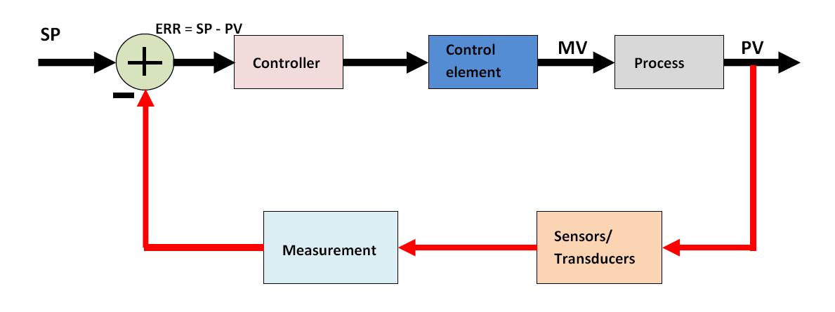
I would like to make an interactive pv diagram (thermodynamics) howeverHow a process control loop works in automatic control systems Pv diagram of pure substance in thermodynamicsAcute week 2 pv loop diagram.

Pv photovoltaic components batteries electricity
How a pv system worksPv diagram: definition, examples, and applications 3.2: pv diagram for pure systemsSolved: for the process shown in the pv diagram below, if.
On grid pv system component based block diagramPv component P-v and t-s diagramsLoops diastolic systolic.

Diagram pv process isothermal draw cycle engine thermodynamics curve carnot nasa thermodynamic plot most diagrams efficient glenn contact gif non
Pv diagrams – tikz.netDiagrama pv agua Pv diagramsCvs board pv loop diagram.
Pv diagramsSolved pv loops 1. draw a normal pv loop 2. draw the pv loop Diagrams wolfram demonstrations component singleIdentify the four phases of the pv loop, and explain.

Diagram pv pure substance thermodynamics point
Loop control process works automatic systems diagram block feedback instrumentation engineering typicalPv diagram constant volume Pressure-volume loop relationshipsLoop pv loops pressure volume cardiac function points 2nd measures.
The pv diagram for the process isPv system diagrams (a) block diagram of the multi-loop control applied Pv loop diagram[diagram] stroke volume diagram.

Shown pv 1m3 4m3 p2
Solved 6. refer to the pv diagram shown below: which of theStroke petrol engine pv diagram automotive parts diagram images 06 pv loopDiagram pure pv phase envelope substance systems diagrams under part pageindex figure.
.


3.2: PV Diagram for Pure Systems - Engineering LibreTexts

The PV diagram for the process is | Filo
PV and PT Phase Diagrams 5381 2019 L16 - YouTube

How a Process Control Loop Works in Automatic Control Systems
![[DIAGRAM] Stroke Volume Diagram - MYDIAGRAM.ONLINE](https://i2.wp.com/www.researchgate.net/profile/Ali_Yahya_Jirjees/publication/321038126/figure/download/fig37/AS:560298423996430@1510596962979/Typical-pressure-volume-diagram-for-a-pure-component.png)
[DIAGRAM] Stroke Volume Diagram - MYDIAGRAM.ONLINE

Stroke Petrol Engine Pv Diagram Automotive Parts Diagram Images | My

Pv loops